Identify the wire part before selecting equipment
Wire forming covers more than one operation. A bent wire clip, a helical spring body, a flat-wire retaining ring and a profiled-wire thread insert have different geometry and stock requirements. Start with the controlled component drawing and material specification, then review the appropriate forming route. A machine category alone does not establish that a finished part can be supplied or approved.
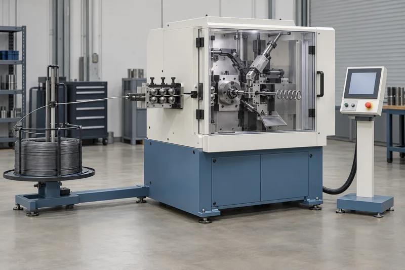
Wire bending is not one universal coiling process
| Route | What to distinguish |
|---|---|
| Wire bending | WAFIOS describes CNC bending equipment for two- and three-dimensional wire or profile parts. Review the required bends, overall envelope, stock and tool arrangement. |
| Spring body coiling | Dedicated coiling equipment forms spring bodies; torsion features, extension loops and end grinding can involve different machines or additional operations. |
| Flat-wire ring or wave-spring coiling | Smalley describes coiling flat wire on edge. WAFIOS separately lists ring and wave-spring equipment for profiled wire. Do not substitute a stamped-ring route merely because the finished part is circular. |
| Profiled-wire thread insert | Böllhoff describes HELICOIL inserts as rhombic-profile wire formed into a spiral. This identifies a specialised construction, not a manufacturing recipe or a claim that the pictured machine produces wire inserts. |
What to review in the equipment arrangement
A production review should distinguish stock supply and preparation, controlled feeding, the forming tools, cutting or end-feature operations, and part handling. WAFIOS lists feed rollers, coiling tools, pitch tools and cutting arrangements on its spring-coiling equipment. Options and tooling are machine- and part-specific; a photographed or named machine must not be treated as a complete production plan.
For a bent wire part, keep the bend sequence and the tool-clearance assessment with the part drawing. For a coiled part, identify section orientation, winding direction, turns, spacing and end construction where applicable. These are review inputs, not operator instructions or preset machine values. Set-up and operation require the actual equipment documentation and qualified personnel.
Connect the route to the existing product
- Spring clips: a wire-formed construction needs a different assessment from a punched and bent sheet or strip clip. The product name alone does not select the route.
- Spiral retaining rings: keep flat-wire section, turn count, internal or external use, end configuration and the mating groove specification together. Coiling the ring is separate from machining its receiving groove.
- Wire thread inserts: identify the required profile, coil geometry and any drawing-defined tang or locking feature. Insert manufacture is separate from preparing a host thread and installing the insert.
Do not infer a wire-coiling route for slotted or coiled spring pins from the word “spring”. Stock construction must be confirmed first. The stamping and forming guide covers separate sheet/strip questions.
Prepare a wire-component enquiry
| Requirement | Information to provide |
|---|---|
| Component definition | Drawing and revision, part identity, units, free-state geometry, required end features and mating-part definition. Identify which dimensions apply before or after assembly. |
| Wire or profile stock | Exact alloy and grade, stock section and orientation, material condition and specified surface requirements. A diameter alone cannot identify flat or shaped wire. |
| Geometry and route review | Bends or coil form, direction, turns and spacing as applicable; required edge/end condition. Keep manufacturing feasibility and any proposed tool arrangement subject to part-specific review. |
| Finished-part acceptance | Controlled dimensional criteria, specified material/treatment/finish records and any separately defined functional test. Record sample review, lot identification and packing requirements. |
| Order scope | Quantity, drawing-defined variants and agreed sample or production scope. Identify missing information rather than assuming a catalogue model or universal capability. |
Forming does not prove spring or retention performance
Geometry, material condition, any subsequent treatment and finished acceptance belong to the selected specification. Do not use the equipment image to infer spring rate, fatigue life, retaining load, groove compatibility, thread strength or installation-tool compatibility. No universal capacity, tolerance, cycle time or treatment setting is offered here. The heat-treatment and inspection guides explain separate review stages, not a guaranteed qualification.
Related products and operations
Equipment category and order-specific records
This guide explains possible part-specific operations. It is not an installed-machine inventory or proof of factory ownership, capacity, certification, stock or supply availability. Send the finished-component requirements for review; the production route and commercial scope must be confirmed for the order.
Technical references
Independent manufacturer resources support the process distinctions. They do not establish an installed machine, brand affiliation or commercial relationship.