Machine the features defined by the drawing
CNC machining removes material to produce the geometry specified for a component. It can be considered for drawing-based shoulders, bores, steps, grooves or secondary features; it is not a required route for every standard fastener. Choose the route around the controlled part, material condition and acceptance requirements.
Turning, milling and secondary operations
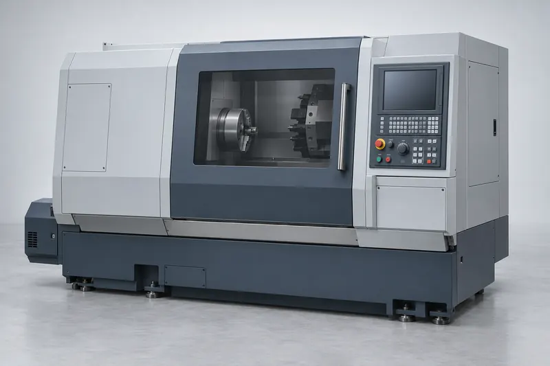
Turning
In conventional turning, the workpiece rotates while a cutting tool produces features such as outside diameters, faces and shoulders. Boring addresses internal cylindrical features. Clamping and access must be evaluated for the particular component.
Milling and drilling
Milling uses a rotating cutter for features such as flats and slots. Drilling and other hole-finishing operations need their own tooling and acceptance review. These operations may use a separate machining centre.
Live tooling is configuration-dependent
Haas describes live-tool and axis configurations that add secondary milling, drilling and tapping on turning centres. This is a manufacturer example, not a specification for the pictured equipment. An ordinary lathe should not be assumed to offer every combined operation.
Separate geometry from the production promise
A machined spacer, bush, shoulder component or special fastener starts with its own drawing. Similar appearance does not establish interchangeability. The drawing must identify the locating surfaces, mating parts, thread requirements and critical relationships between features.
There is no universal tolerance or surface-finish capability promised on this page. The actual machine, tooling, workholding, material and inspection method must be reviewed before agreeing finished requirements.
Plan the part-specific sequence
- Confirm the drawing revision, material designation and starting condition.
- Identify datums, clamping surfaces, tool access and the features that require machining.
- Review turning, milling, drilling and the selected thread-production route separately.
- Agree the sequence relative to treatment, deburring and coating.
- Review samples and verify the agreed finished geometry and records.
This is a planning overview, not a CNC program or set-up instruction. Speeds, feeds, guarding and maintenance belong to qualified personnel using the actual equipment and tool instructions.
Prepare a machining enquiry
| Review point | Information to confirm |
|---|---|
| Drawing | Revision, datums, dimensions, tolerances, feature relationships, mating geometry and any model-versus-drawing priority. |
| Material and stock | Material designation, starting condition, stock form and treatment sequence to be reviewed for the component. |
| Threads and surfaces | Thread system, pitch, fit, threaded length, surface finish, edge breaks and burr restrictions. |
| Acceptance | Agreed dimensional checks, critical-feature inspection, sample review, quantity and lot identification. |
Connect the drawing to the product
For an external formed thread, compare thread rolling. For a tapped internal thread, see nut tapping. These are route choices to assess, not interchangeable processes or installed-equipment claims.
Request the finished component, not a machine
Provide the drawing and acceptance requirements for feasibility review. Equipment appearance does not establish ownership, precision, capacity, certification or supply availability.
Technical references
Independent equipment and technical resources. These references do not establish installed equipment or a commercial relationship.